Every Wrench Has a Story: The Retired Machinist Rebuilding His Garage in Millimeters
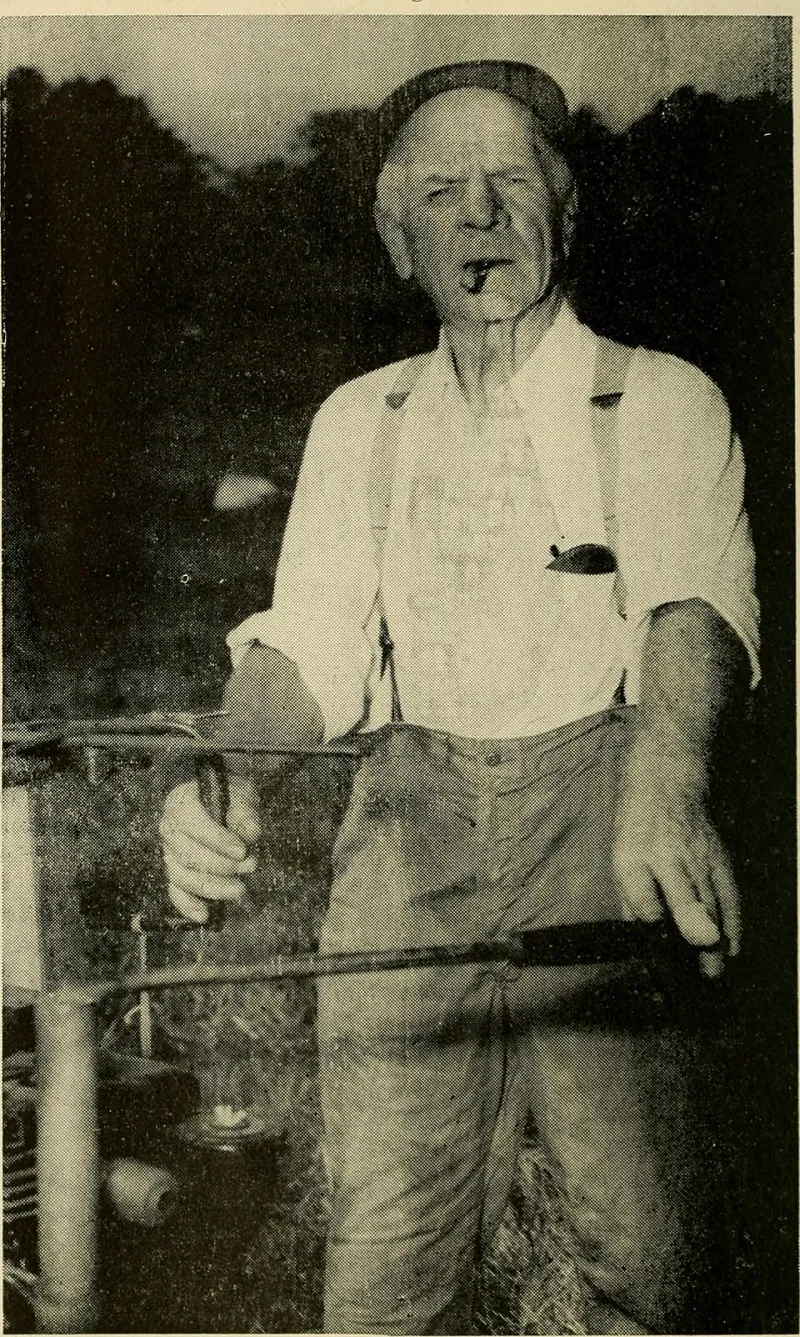
Photo: Internet Archive Book Images, No restrictions, via Wikimedia Commons
Hank Prewitt's garage in Rockford, Illinois, smells like way oil and old cardboard. There's a Bridgeport in the corner that he swears still holds a tenth, a Kennedy stack of drawers that has outlived three trucks, and a pegboard wall covered in tools that look like they've been through something. Because they have.
Prewitt retired in 2025 after 41 years as a machinist and tool-and-die hand. Fourteen months ago, he opened Blender for the first time. His project is simple to describe and slightly insane to execute: rebuild every single object in that garage as a 1:1 3D model, dimensionally accurate, correctly weathered, and organized in a library he can hand off.
Not a stylized homage. Not an art piece. A tool crib you could measure.
The One Rule He Won't Break
"One to one means one to one," Prewitt said, tapping a 6-inch dial caliper on the bench. "If a jaw is 24.6 millimeters, the model is 24.6 millimeters. Not 25 because it's easier."
That constraint sounds trivial until you try it. Real tools aren't neat. A combination square's blade has a slight bow. A spade bit's flutes are uneven because the factory ground them uneven. Prewitt models the imperfections because he measures the imperfections — and his measurement habit is where most hobbyists would tap out.
His bench setup is modest: a digital caliper, a 0–1 inch micrometer, a set of radius gauges, and a $9 thread pitch gauge from a hardware store bin. For profiles, he traces the silhouette of a part onto graph paper, photographs the tracing flat, and imports it as a reference plane. "Ten minutes with paper beats an hour guessing in the viewport," he said.
The Reference Ritual That Saves the Model
Prewitt photographs every tool before he models it, and he does it the same way every time. It's a routine he picked up from inspection paperwork, not from a tutorial.
- Raking light, not flat light. A single shop lamp dragged low across the surface to make small dings and chamfers visible.
- A scale bar in frame. Blue painter's tape cut exactly 100 mm long, laid next to the tool. "When a photo looks off later, that tape tells me if it's perspective or my model."
- Five angles, minimum. Front, back, both sides, and a top-down orthographic-ish shot from a step ladder.
- A written note per part. One index card listing the tool, its measured length, any missing pieces, and the date. Those cards live in a shoebox and get typed into a spreadsheet the same evening.
That spreadsheet is the unglamorous heart of the whole thing. Each row tracks model status, polycount, texture set, and whether the tool has been verified against the physical object a second time. Prewitt calls the second pass "the recheck," and roughly a third of his early models failed it.
Wear Marks Are the Whole Point
On screen, Prewitt's wrenches look used. Chrome is rubbed thin at the open end. The knurling on a set of taps has a dark grease patina in the valleys and bright polish on the peaks. There's a bloom of rust on a pipe clamp that he refused to clean up.
He builds that in with three passes: a base roughness map from photos, an ambient occlusion bake to catch the geometry that collects grime, and a hand-painted roughness layer for the high-touch areas. The temptation, he admits, is to overdo it.
"New guys candy-cane the rust," he said. "Real wear is where hands and work happen, and nowhere else. If you can't explain how a mark got there, take it out."
That question — how did this mark get here? — is the single best texture discipline he can pass on, and it costs nothing but honesty.
What Hard-Surface Modelers Keep Getting Wrong
Prewitt has now watched enough tutorials to have opinions, and his biggest one is about edges. Hobbyist hard-surface models tend to look like CAD drawings that learned to render. Real machined parts look like decisions.
"Every corner on a real tool is a chamfer, a fillet, or a draft angle, and each one exists because a cutter had to get in there," he said. "If your edge flow follows the manufacturing, the shading takes care of itself."
His practical advice: model the cutter's path mentally before you place the first loop. Keep chamfers at a consistent real-world width (he uses 0.5 mm for most hand tools). Don't boolean something you could have modeled with a proper support loop. And treat tolerance as a modeling constraint — if the real part has a slip fit, the model should show a gap, not a shrug.
The Tool Crib Goes Public
Prewitt's library lives in a shared cloud folder and, for people who prefer it, on a labeled thumb drive that circulates through the Rockford-area makers' club he joined last spring.
The uses surprised him. A member who can't easily get to the shop uses the models to plan a bench layout in VR before buying lumber. Another built CNC hold-down fixtures around Prewitt's accurate vise jaw dimensions. The local community college's shop class pulls his clamp models for a safety orientation deck. Someone even printed a scale model of the pegboard as a joke gift.
"I figured it was a personal project," he said. "Turns out other people needed a garage they could measure."
At his current pace — roughly three tools a week, more for anything with a gear train — Prewitt figures the garage is three years from done. He's not rushing. The recheck doesn't care about deadlines.
Anyone who models props for a living could borrow his method tomorrow: measure, photograph with a scale bar, log everything, and don't invent a scratch you can't explain. The tools on your shelf are already a reference library. You just haven't calibrated it yet.